

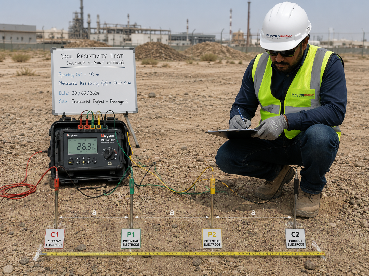
Every earthing calculation begins with one number: soil resistivity. Assume it, and every figure downstream inherits the error.
What the survey actually tells you
A Wenner four-pin traverse at increasing probe spacings gives apparent resistivity versus depth. Fitting a two-layer model to that curve tells you whether a 3 m rod is sitting in a dry resistive blanket or reaching a conductive stratum — the difference between an electrode that works and one that does not.
Method that survives review
- Minimum two perpendicular traverses per area, more on large or geologically varied sites.
- Spacings stepped from 1 m out to at least the expected grid depth of interest.
- Record temperature, moisture, recent rainfall and probe positions on a marked-up layout.
- Repeat suspicious readings; buried metalwork corrupts a traverse quickly.
The seasonal trap
Resistivity in arid regions can rise several-fold between wet and dry conditions. A system commissioned after rain that passes at 0.9 Ω may sit well above target four months later. Either survey in the worst-case season or apply a documented correction factor and design with margin.